Photo-Fuel-Cell:
Production of electricity and hydrogen by photocatalytic degradation of
organic wastes in a Photoelectrochemical cell
Introduction
Production of electricity and hydrogen by
photocatalytic degradation of organic wastes in a Photoelectrochemical (PEC)
cell is an attractive project with double environmental benefit: waste material
can be consumed and solar radiation can be converted into useful forms of
energy, such as electricity and hydrogen.
Definitions
Production of hydrogen by degradation of
organic substances in the presence of a photocatalyst can be distinguished into
two major categories:
(1) Photocatalytic (PC) production of hydrogen By this term, we usually mean
production of hydrogen by heterogeneous photocatalysis using powdered or
supported, pure or combined photocatalysts. As shown in Fig.1A, the
photocatalyst is excited by absorption of photons, which create electron-hole
pairs. Holes oxidize the photodegradable substance R, either directly or
through radical intermediates, typically OH·, which are very efficient hole
scavengers. Oxidation liberates hydrogen ions, which can be reduced by
photogenerated electrons producing molecular hydrogen. The photodegradable
substance can simply be water itself, however, the product of oxidation of
water is oxygen, which interacts with hydrogen regenerating water. Thus it is difficult to produce hydrogen by
photocatalytic water splitting, since hydrogen and oxygen must be spatially
separated. This can be only managed in a
PEC cell, as it will be explained below. As a matter of fact, in order to
detect photocatalytically produced hydrogen, it is necessary to apply anaerobic
conditions. Furthermore, the rate of
hydrogen production may increase by two orders of magnitude in the presence of
a fuel than in pure water.
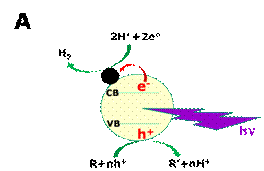

Figure 1. Schematic representation of the
Photocatalytic (A) and the Photoelectrochemical (B) production of hydrogen. The
black full circle in A represents a co-catalyst (usually, a noble metal
nanoparticle). The co-catalyst scavenges photogenerated electrons. In B,
(Photo)anode electrode is on the left side and cathode on the right side.
Oxidation and reduction may only take place when the photogenerated
electron-hole pairs possess the necessary oxidation/reduction potential. In B, production of hydrogen is illustrated by
the example of ethanol employed as fuel. Oxidation of ethanol takes place at
the anode electrode at high pH while reduction of water takes place at the
cathode. Photoanode bears photocatalyst and cathode bears an electrocatalyst.
(2)
Photoelectrochemical production of hydrogen In this
case, hydrogen is produced in a PEC cell. The following three components are
the main components of a PEC cell: (a) The anode electrode, which carries the
photocatalyst and thus it is usually named “Photoanode”. When the photocatalyst is an n-type
semiconductor, which is almost the exclusive case, the photoanode produces
electrons, i.e. it is the negative electrode.
Oxidation reactions take place at the photoanode; (b) The cathode
electrode, which carries the electrocatalyst, i.e., a material, which
facilitates transfer of electrons from the cathode to the liquid phase.
Reductive interactions take place at the (dark) cathode, for example, reduction
of hydrogen ions to molecular hydrogen; (c) The electrolyte, which is added in
order to increase conductivity and define the pH. The photoelectrochemical production of
hydrogen is schematically illustrated in Fig.1B. Photons are absorbed by the photoanode
generating electron-hole pairs. Holes oxidize the photodegradable substance, as
above, liberating hydrogen ions, which diffuse in the liquid phase. Electrons
are channeled through an external circuit towards the cathode, where they
reduce hydrogen ions producing hydrogen molecules. At high pH, as illustrated in Fig.1B, no
hydrogen ions can be detected in solution but molecular hydrogen is produced by
reduction of water. Thus production of hydrogen is accompanied by flow of
electrons, i.e. an electric current, in the external circuit. Hydrogen, of
course, is detected in the absence of oxygen.
Otherwise, in its presence, hydrogen is retained regenerating water.
Water-splitting in a PEC cell does lead to hydrogen production, since the
oxidation site, i.e. the photoanode, is spatially separated from the reduction
site (cathode), thus O2 and H2 can be easily separated.
The Photofuelcell In the presence of oxygen, for example,
aerated liquid phase, no hydrogen can be
detected. In that case, current can still flow in the external circuit of the
PEC cell. Electrons arriving at the
cathode reduce O2 (see below). Then the cell acts as a Photofuelcell
(PFC). A PFC consumes an organic substance, i.e. the fuel, and utilizes light
energy to produce electricity.
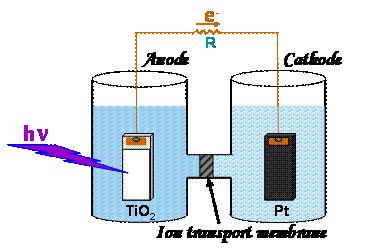
Figure 2. Schematic representation of an H-shaped PEC
cell with a TiO2 anode and a Pt cathode, divided into two
compartments by an ion-exchange membrane.
The current flows through an external load of resistance R.
Basic configuration of a PEC cell
The basic configuration of a PEC cell is
schematically shown in Fig.1B and Fig.2.
The cell comprises a photoanode that carries a semiconductor
photocatalyst, a (dark) cathode that carries the electrocatalyst and the liquid
phase that carries an electrolyte. Anode
and cathode are connected through an external load. When the photocatalyst is
an n-type semiconductor and the electrocatalyst is a noble metal, as it is the
usual case, the photoanode acts as the negative electrode and the cathode as
the positive electrode, i.e. electrons move from the anode to the cathode. The direction of the external current, of
course, depends on the electric potential of each electrode. The electrochemistry of a PEC cell is fairly
complicated. However, even an
inexperienced experimenter can make a cell run by taking into account the
following elementary considerations.
When the cathode is in contact with an aqueous electrolyte at zero pH, its potential depends on the
presence or not of oxygen. In the
absence of oxygen, cathode behaves as a hydrogen electrode, the potential of
which is conventionally taken equal to zero.
In the presence of oxygen, the cathode behaves as an oxygen
electrode. Its potential is then
affected by the following reductive reactions
O2+4H++4e-®2H2O (+1.23 V) (1)
O2+2H++2e-®H2O2 (+0.68 V) (2)
This means that its value is between 0.68 and
1.23 Volts. The potential of the anode
depends on the Fermi level of the semiconductor photocatalyst. In the case, for
example, of titania, which is the most usual case, the conduction band at zero
pH has a potential, which is slightly positive and when excited it becomes
slightly negative. In the absence of oxygen, taking into account also the
unavoidable losses, this potential difference is too weak to make the cell run
spontaneously. Therefore, an external electric bias is required. By bias, is
meant an external electric potential, which is added between the two
electrodes, as in Fig.3, in order to
increase the electromotive force driving electrons from the anode to the
cathode.
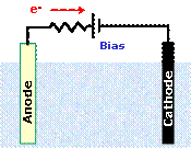
Figure 3. Schematic
representation of the polarity of an external electric bias for a PEC cell
Indeed, in such cases, various possibilities of
additional bias have been proposed, the most notable ones being those, where
the additional voltage is provided by renewable energy devices, like photovoltaic
cells. In the presence of oxygen, no
bias is required, since in that case a potential difference of several hundreds
of mV between the two electrodes could be obtained without much of an
effort. Thus the Photofuelcells, which
function in the presence of oxygen, are spontaneously running devices. The
above electrode potentials, as already said, correspond to zero pH value. At higher
pH and at room temperature, the potential of both electrodes drops according
to the following equation:
DV(Volts)= -0.059x(DpH) (3)
Thus if the pH increases by the same amount for
the whole liquid phase of the cell, the variation of the potential of both
electrodes is the same, so the difference between the electric potential of the
two electrodes remains the same. If the
pH of the electrolyte around the anode is basic and that around the cathode is
acidic, then the potential difference between the two electrodes
increases. In that case, we say that the
cell functions under chemical bias. The
potential difference between the two electrodes reflects on the measured
open-circuit voltage Voc of the cell, which corresponds to infinite
resistance R in Fig.2. Thus Voc
can be much larger than 1.0 Volts, when chemical bias is applied. Chemical bias can be applied when the cell is
structured into two compartments (as in Fig.2) communicating through an ion
exchange membrane, for example, proton-transporting Nafion membrane. However, chemical bias is not a
self-sustainable situation since chemical reagents must be continuously added
in the two compartments to keep pH difference, which is otherwise eventually
removed by ion transport through the membrane.
Further chemical bias is offered to the system when a fuel, i.e. a
sacrificial agent that retains photogenerated holes, is added to the cell. In that case, the consumption of holes
increases the number of photogenerated free electrons that makes anode
potential more electronegative. This
electric-potential variation reflects on the increase of the Voc of
the cell. Indeed, in a cell running with
the same pH value in the anode and the cathode compartment, in the presence of
ethanol or glycerol Voc becomes about 0.3 Volts larger. The above discussion shows that it is very
easy to run a PFC both with and without fuel, simply by shining light on the
photoanode. It is understood that this
light must contain the appropriate wavelengths necessary to excite the photocatalyst.
Further information on the same
subject can be found in the following review:
Production
of electricity and hydrogen by photocatalytic degradation of organic
wastes in a Photoelectrochemical cell. The concept of the Photo-Fuel-Cell. A review of a re-emerging research field:
Panagiotis Lianos, J.Hazardous
Materials, 185(2011)575-590 ![]() doi:10.1016/j.jhazmat.2010.10.083
doi:10.1016/j.jhazmat.2010.10.083
Page
updated August 2011